Graphic Tool Settings
In the settings of Graphic Tools (Global Configuration) you can find everything that is needed to configure like Layers, Smart Markers, Icons and also here you can upload different graphic files for floor plans, devices and systems to use later while you create new graphics.
Accessing Settings
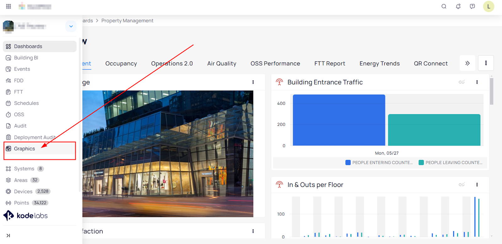
To get into Graphic Tool Settings first you need to navigate to “Graphic Tool” by clicking on the module on the main left pane on KODE OS:
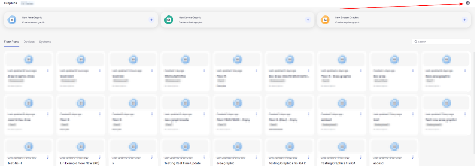
When you are within the Graphic Tool in the upper right corner click on the gear icon:
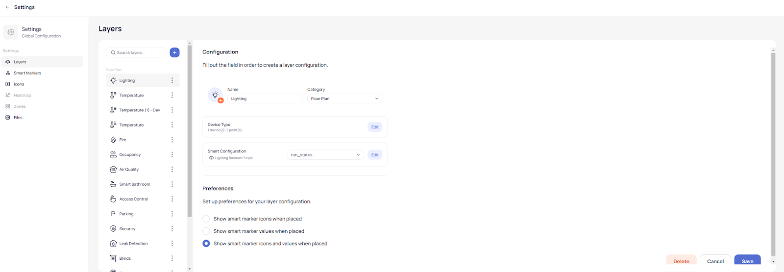
Here you find yourself within the settings page where you can upload files for Layers, Smart Markers, Icons and also preconfigure them.
Layer Settings
In the layers settings you can configure the behavior of a specific layer according to its type.
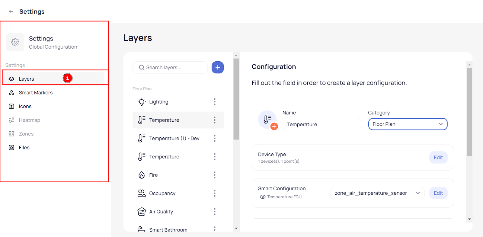
- For example if you want to have a temperature layer created first you select Layers option on the left pane:
After you select the layer you can create a new layer by clicking on the blue plus button, or you can edit an existing one simply by selecting it.
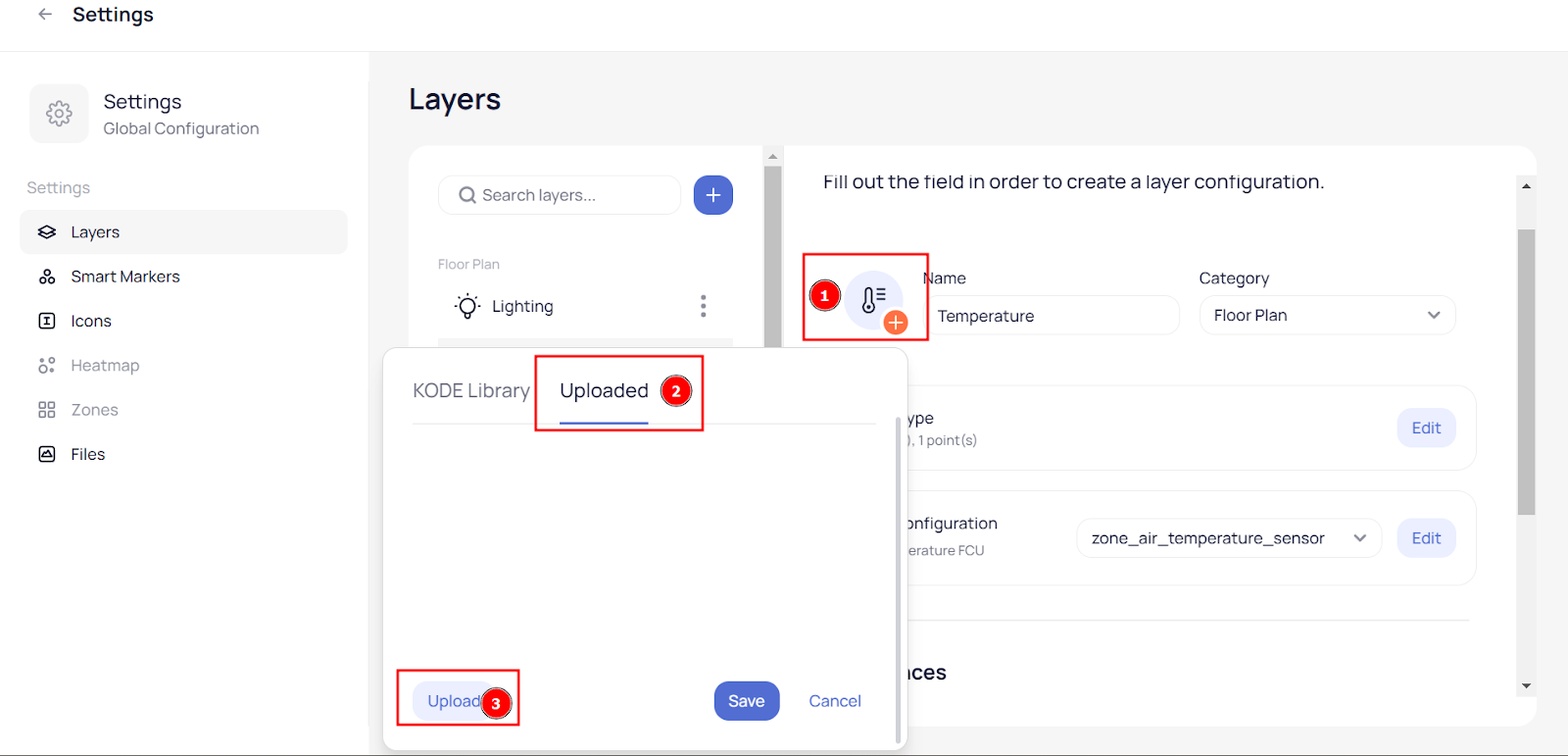
You can select an icon for your layer from KODE library or you can upload a custom icon by going on the Uploaded Icon and selecting previous uploaded one or you can upload a new one by clicking upload:
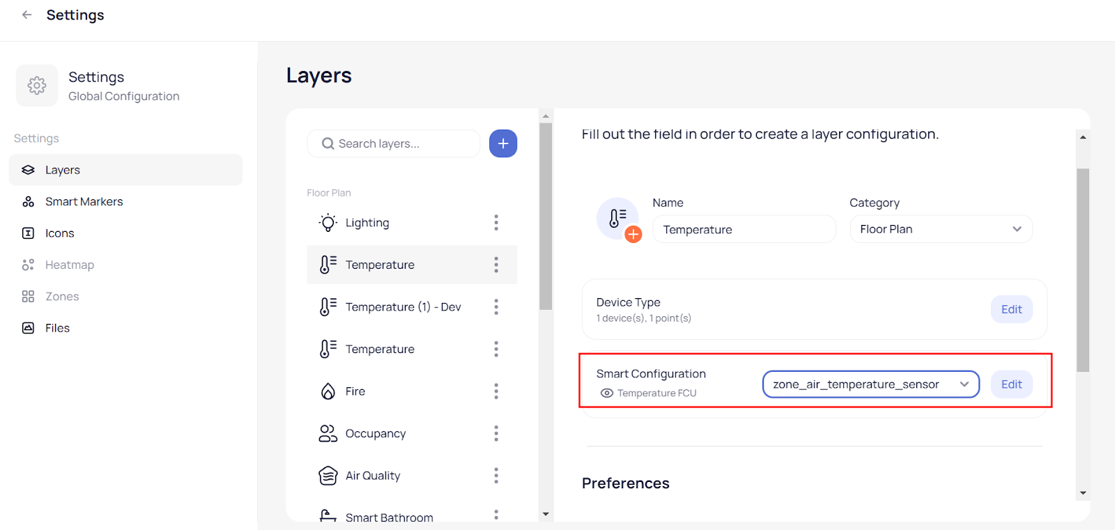
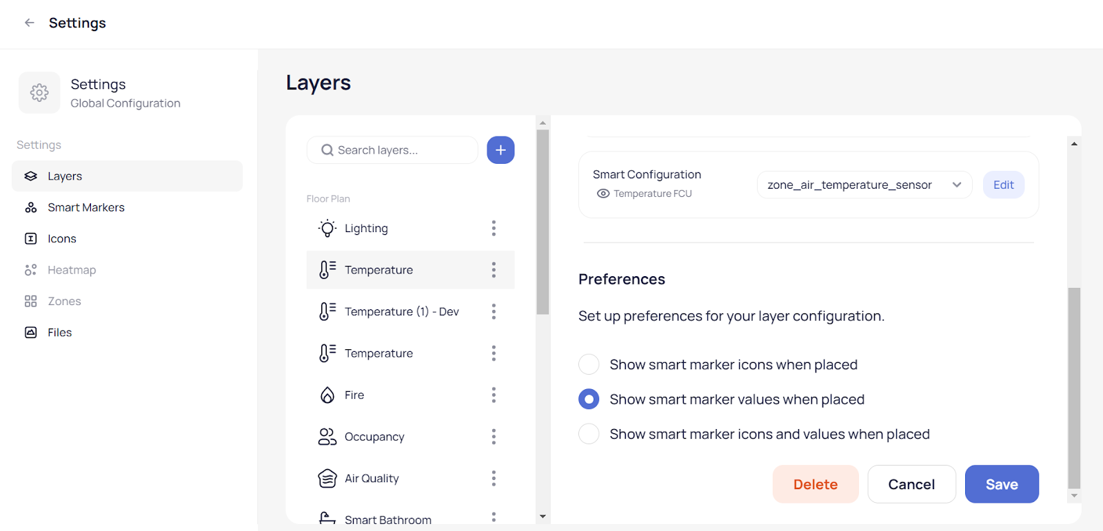
Since you selected to edit or to create a temperature layer you can select Device Type and then choose a point field. This will ease your process while you create a Floor Plan graphic which automatically adds the point to the marker when you place devices across the Floor Plan according to the layer type:
Also you can select Smart Configurator where the system will load icons according to the temperature, select the point and click on Edit:
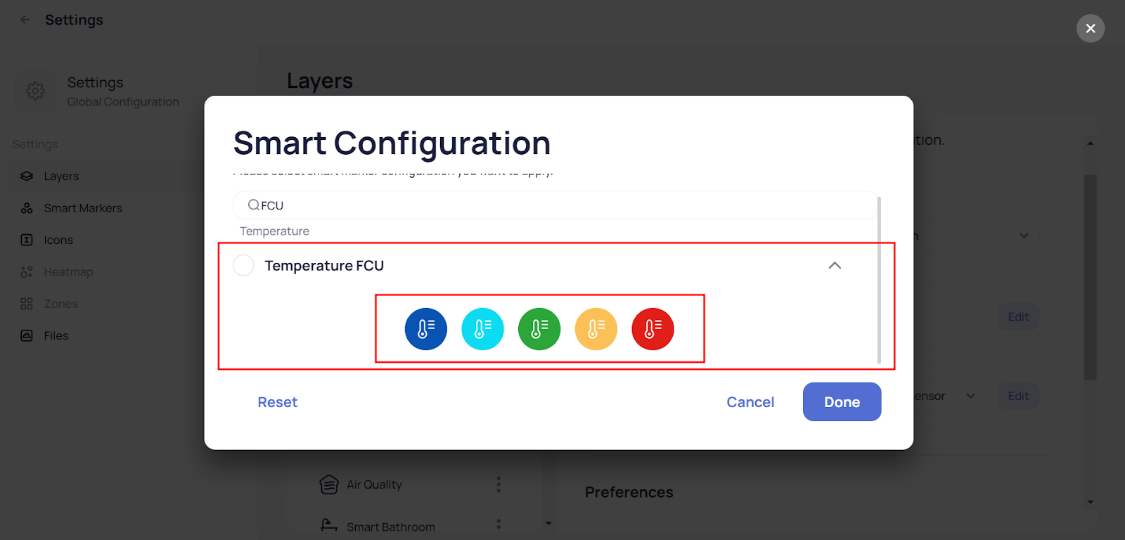
After you click Edit select the icon configuration that correspondents with the layer type and click done:
In the end you can choose the preferences on how you want to appear where listed you find these three options:
Smart Markers Settings
In the Smart markers settings you can configure or edit the behavior of the icons that will appear when you add them
on any graphics.
You can find pre-configured Smart Markers in our library based on the most use cases or you can create a new one.
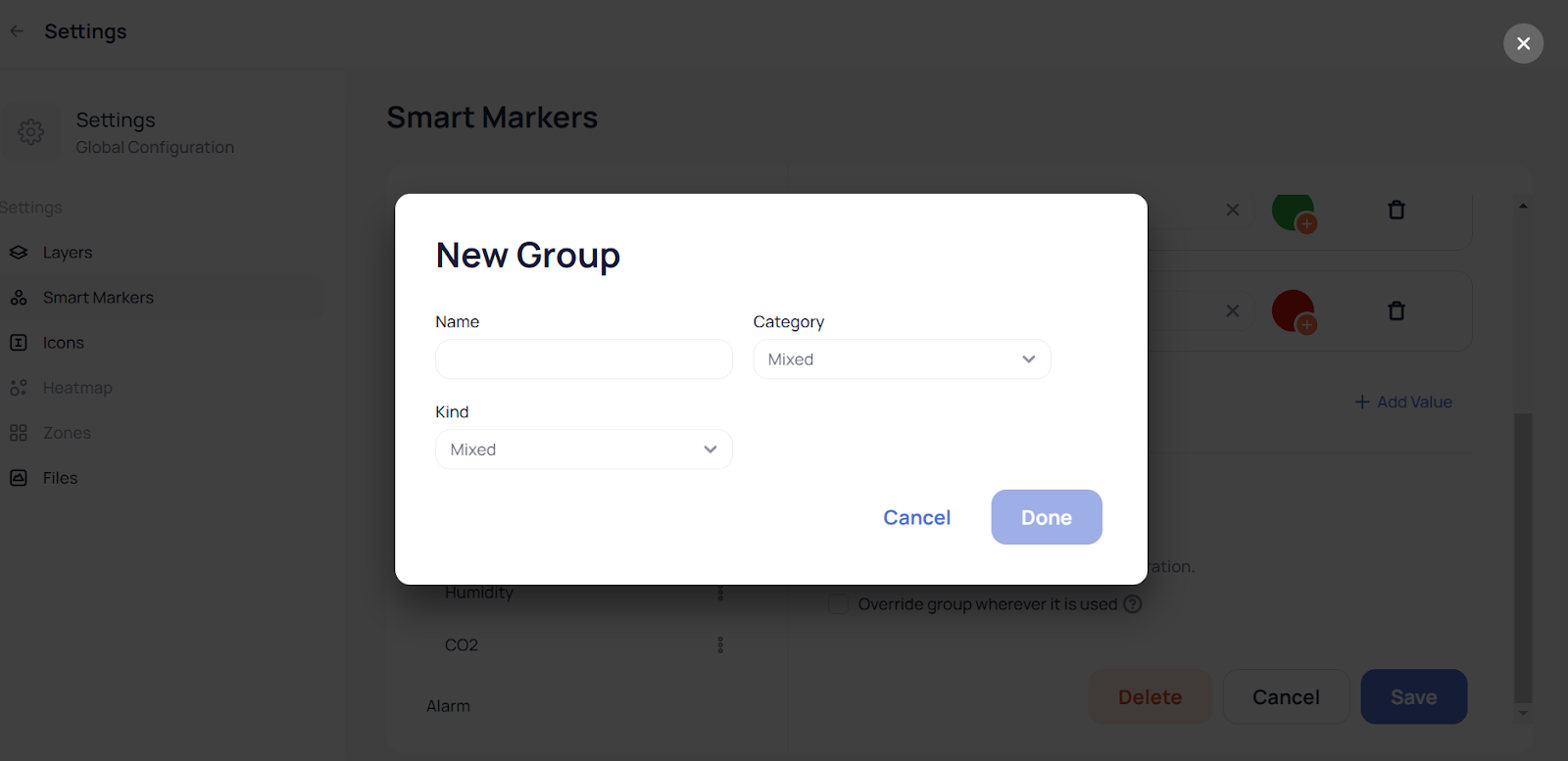
To create a new Smart Marker simply click on the plus icon in the smart markers listing and fill the name, select category and the kind if the values are Number or String/Boolean:
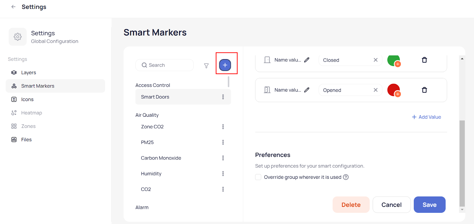
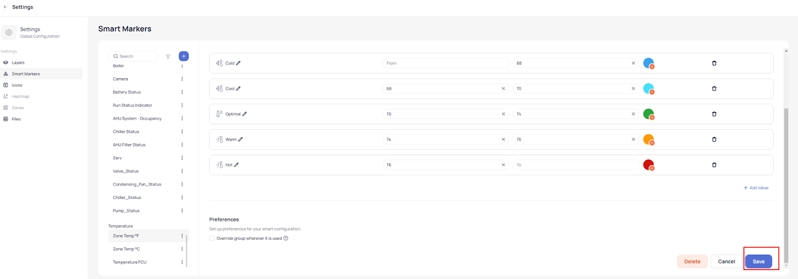
Then fill the values/ranges from where the smart icon will interact by clicking “Add value”:
After you complete values click done and you will be redirected to just created or selected Smart Marker windows where you can review it or edit. To finalize the work you click on the Save button:
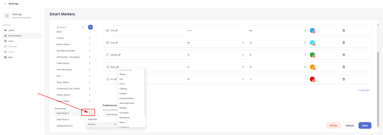
On the left side where all Smart Markers are listed you can click on the three dots of the Smart Marker you want and there will be shown two options that gives you the ability to Duplicate it or to move it to another Category:
Icons Settings
In Icons settings you can view our library of icons or you can upload custom ones.
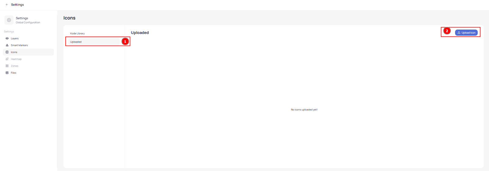
To upload a custom Icon click on “Uploaded” and then click the “Upload Icon” button:
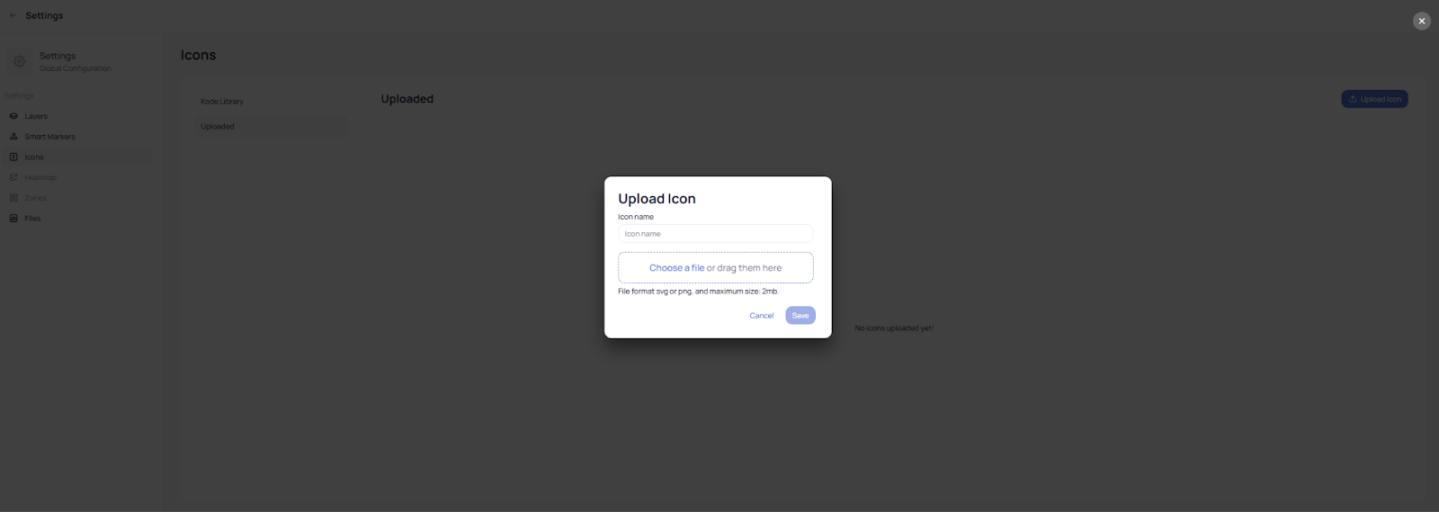
After you click the button the upload window will appear requiring you to input the name for the icon and to browse the icon file (file should be in svg or png format not exceeding 2MB):
After naming the icon and selecting a file simply click Save and your custom Icon will be available to use and select in the graphic tool.
Files settings
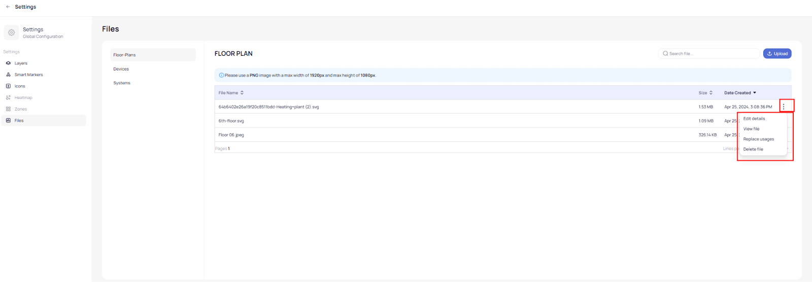
In Files Settings you can browse your uploaded graphic files that you are using in Floor-Plans, Devices and Systems. Files are also categorized here in: Floor-Plans, Devices and Systems.
You can upload files within each category for a later use while you will be creating any graphic.

Recommended file format is PNG with max width of 1920px and max height of 1080px.
On each file you can click on the three dots to open a specific option menu:
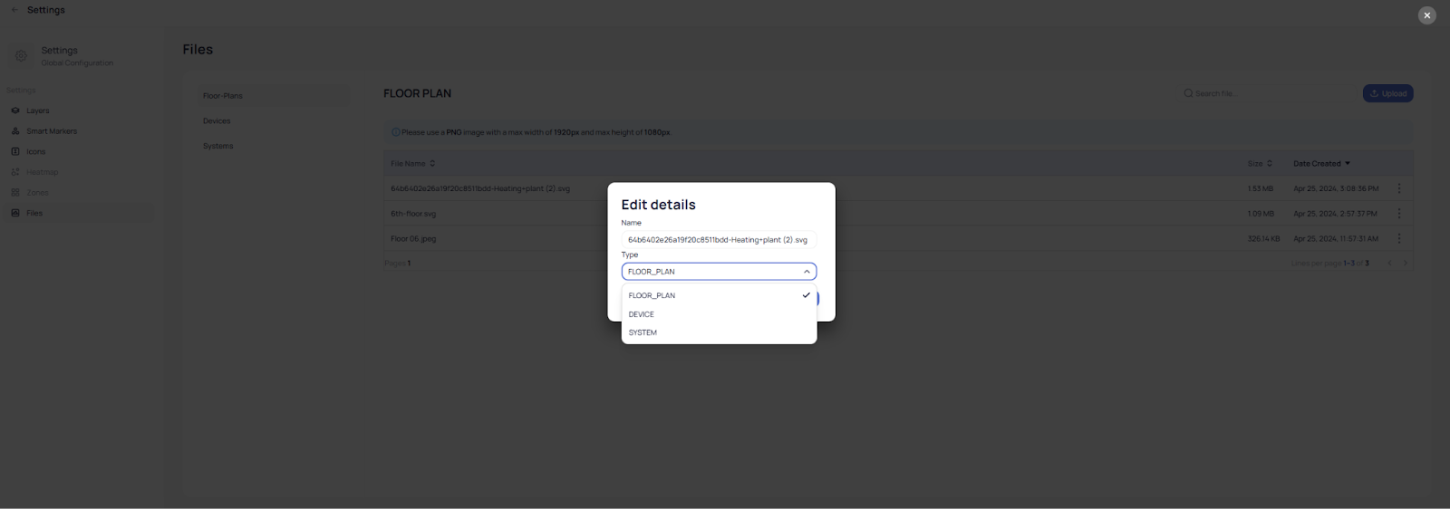
In “Edit details” you can change the name of the file and it’s type:
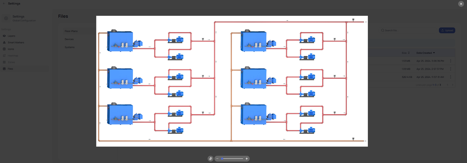
In “View file” you will be able to view a file and rotate it:
In “Replace usages” you can replace the image file with another file of your choice and the Graphic Tool will replace the image file everywhere where it is being used.
Related Articles
Device Graphic
Device Graphic is a powerful tool for visualizing your building's HVAC system in real time. It allows you to monitor and control your AHU, VAV, and HVAC devices and their components, all from a single interface. Overall, Device Graphic is an ...System and Floor Plan Graphic Customization
You can add texts into floor plans with different fonts, draw custom shapes using the pen tool, add images and different colors to create gorgeous graphics that you can customize with powerful features. You can enhance the design of a layout in a ...Customizing Markers and Icons
The Graphic Tool feature provides different tools which allow you to optimize and make floor plans more intensive from where you can view and spot devices’ performance with a single sight. This will give you an overall visual perspective of what is ...Add Custom Icons
To add custom icons and ranges to represent each device type and value into a system or floor plan follow the below steps: Navigate to Admin module by clicking on the profile icon from the left main navigation bar. From the left side menu of the ...Graphics Summary
Module summary We’re thrilled to announce that Graphics creation as we know it has been completely transformed. There’s a graphics builder we’ve been cooking that gives you the ability to build System and Device Graphics and customize floor plans ...