Functional Testing Tool Creators Guide
Creators Guide
Table of Contents
Scaling to more complex use cases 20
Introduction
This guide serves as an end to end walkthrough for users looking to create their own Functional Testing Workflows inside of KODE OS. We will introduce the concept of functional testing, showcase goals and examples, provide a scalable architecture for workflows, describe all their components and walk through the design build process.
Best of luck on your functional testing journey! May this guide create great success for you and/or your customers!
What is Functional Testing?
Overview
Functional Testing is a product inside of KODE OS which allows for continuous and automated testing of building systems. These tests, or workflows as we call them, are designed using a drag and drop logic builder inside of KODE OS. The primary use case for functional testing is digital commissioning of HVAC systems for functional components or against a sequence of operations. Once your workflow is created, you will be able to test equipment on demand in real time or schedule for a specific date time in the future as desired. This guide focuses only on creation of workflows.
Workflow Example
VAV Damper Operation
VAV Damper Operation is one the most common functional testing workflows in KODE Labs library. This workflow will test a VAV box for its damper operation. Closing the damper, measuring the resulting airflow to verify functional operation and then opening the damper and once again measuring the airflow to verify functional operation.
The underlying workflow engine can be utilized to build many different tests relevant to all types of equipment across many building types (commercial, retail, healthcare)across a wide variety of device types (VAV, FCUs, AHUs, Lighting, and more) to ensure operational excellence, energy efficiency, and superior client experience. This guide walks you through how to build your own test for your own use cases.
Common Use Cases
There are many use cases for functional testing. We outline a few in this guide to showcase the practical value of the tool and inspire designs for future workflows.
Continuous Commissioning for Commercial Buildings
Commercial Buildings often have 100s or 1,000+ terminal units (VAVs, FCUs, etc) which are used to directly manage comfort inside of tenant spaces. The large volume of equipment and location inside tenant spaces makes it difficult to check during regular preventative maintenance checks. Clients are creating functional testing projects to commission their equipment every heating season and every cooling season to proactively identify issues and fix them to ensure the most energy efficient operation and best client experience.
Functional Testing for Retail
Retail Locations have to service rooftop units and other equipment at scale and every truck roll adds up! Functional Testing is being used before initiating the truck roll to validate the expected failure and then is being run immediately when service is complete to ensure the job was done correctly and avoiding costs from sending a truck back out to fix the next time the equipment tries to execute its sequence of operations.
Data Driven Commissioning For New Construction
While traditional commissioning is common on new constructions, the large volume of equipment makes it too expensive or too timely to have a commissioning agent check every single device. Functional Testing is being used to prioritize the time and effort of the commissioning agent by first running a digital check on the systems and having the commissioning agent re-test the devices that failed instead of spot checking 10-15% of equipment in the building and hoping the rest are functional.
Workflow Architecture
Now that we have motivated the use cases for Functional Testing, let’s get into the details of what a workflow is, how to build one, and provide a scalable architecture to design custom workflows.
What is a workflow?
A workflow represents the end to end test or sequence of operation to be performed by the equipment. The workflow specifies everything from equipment and point requirements, reading of the sensor inputs, commanding the equipment, monitoring the sensors, calculating the success criteria and outputting all text.
Components of a workflow
In KODE Labs standard architecture, every workflow has the following components
Device Type
Sensor Inputs
Required States
User Inputs (Parameters)
Initial Condition Logic
Pre-Condition Logic
Sequence Logic
Release
A high level sketch of how these components logically flow together and definitions for each are provided below.
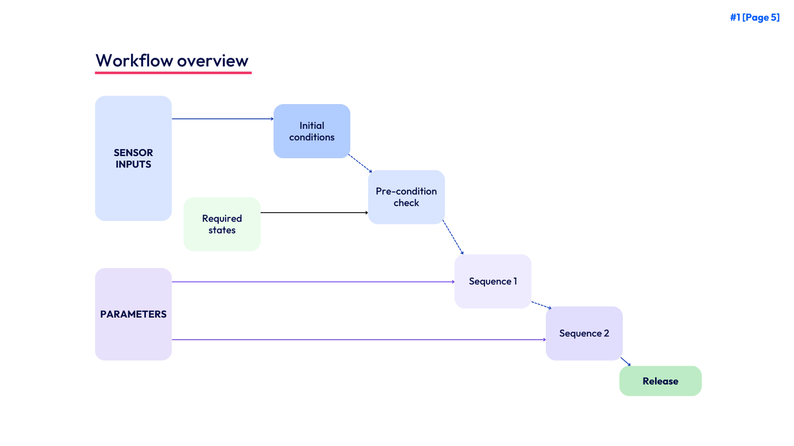
Sequence Architecture
Sequences are the major building block for functional testing workflows. This is where individual mechanical components are tested for their command and response, pass / fail results are generated, and text output is generated for analysis by the end user. Sequences are typically isolated down the smallest individual component of the device that is desired to be tested and scored.
A high level sketch of how these components logically flow together and definitions for each are provided below. For simplicity sake on the sketch, we show only the lines for the logic and omit the lines used to create the string builders. We mark the string builders in orange to differentiate them from the logic blocks.
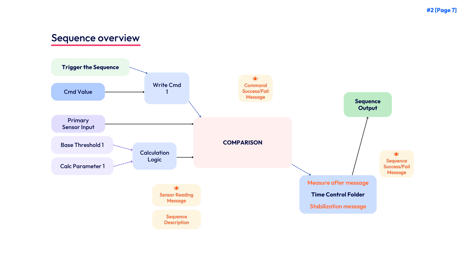
Components of Sequence
Every sequence in the KODE Labs standard architecture has the following components
Trigger
Write Command(s)
Command Value
Primary Sensor Input
Threshold(s)
Base Threshold(s)
Calculation Parameter(s)
Calculation Logic
Calculated Threshold(s)
Comparison(s)
String Builders
Sequence Description
Command Success / Fail Message
Minimum Duration Message
Sensor Reading Message
Stabilization Message
Sequence Success / Fail Message
Sequence Output
Building A Workflow
Now it is time to build a workflow! This guide will focus on making use of the KODE Labs standard architecture and how it can be adapted based on the conceptual design of a new test. Throughout this section we will use the specific case of VAV Damper Operation as an example and map each item to the definitions provided in the workflow and sequence architecture sections.
In addition to the guide below, there are the following resources to assist you in workflow creation.
Workflow Worksheet - An editable page that you can copy and customize as you plan your own workflow design.
Video Guide to the Workflow Worksheet - A short 10 minute walkthrough of the workflow worksheet and how to adapt it to your use cases.
Video Guide to KODE Workflow Creation - A 40 minute step by step video guide to building your first functional testing workflow.
Conceptual Design
The first step in creating a new workflow is to create a conceptual outline of how the equipment should be tested. The core components are to define each sequence, the write commands, and success criteria. For VAV Damper Operation, we drew the following sketch.
Pre-Condition Check
Here we ask ourselves what states should the equipment be in order to ensure that a damper operation test will produce a valid result on a VAV. In the sketch above, we specify that we must check the VAV Occupancy, AHU Occupancy, and AHU Pressure. In this case it’s implied that the VAV and AHU must be Occupied in order to proceed. We know we need sufficient pressure from the AHU, but recognize that it will vary from building to building and so we leave the specific requirement as a user adjustable parameter.
Once we confirm the pre-conditions of a successful test, we are ready to proceed to the first sequence.
Sequence 1
The minimum points needed to define a sequence are the write command, sensor inputs, and threshold for comparison. We have chosen for our first sequence to close the damper which results in the following specifications.
Sequence 2
We specify the same components for the Open Damper sequence.
This leads us to the final step in the conceptual preparation which is to classify all the different points into the categories of sensor inputs, required states, parameters (user input), and write commands. Knowing these in advance will make it easier to build the workflow as each category uses a specific type of logic block. Our categorization is below.
Building a Workflow
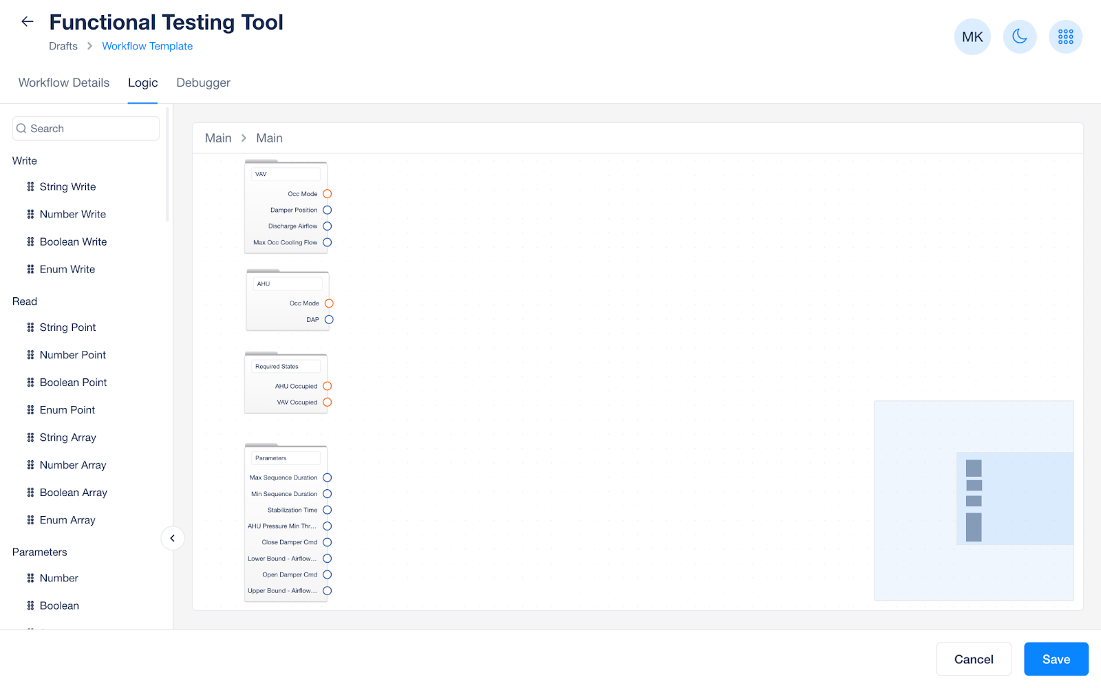
We are now ready to begin building the workflow in the KODE OS workflow builder! We are going to start from the main folder of our workflow.
The first step is to populate our main folder with the points from the table above. We use sub-folders for device types, required states, and parameters to keep us organized. The write commands will be used later inside the specific sequences.
The next step is to use the folder template for initial conditions, pre-condition checks, and any number of sequences. We will connect the main inputs and outputs and build the high level structure for the workflow.
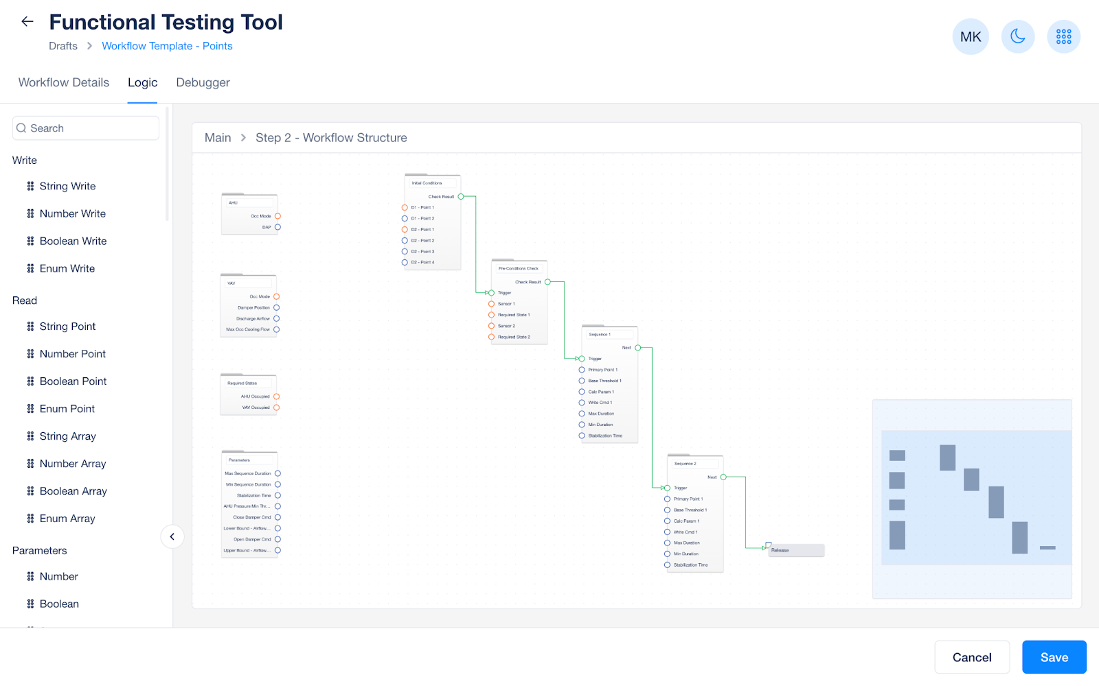
Our next step is to connect our points into the appropriate folders.
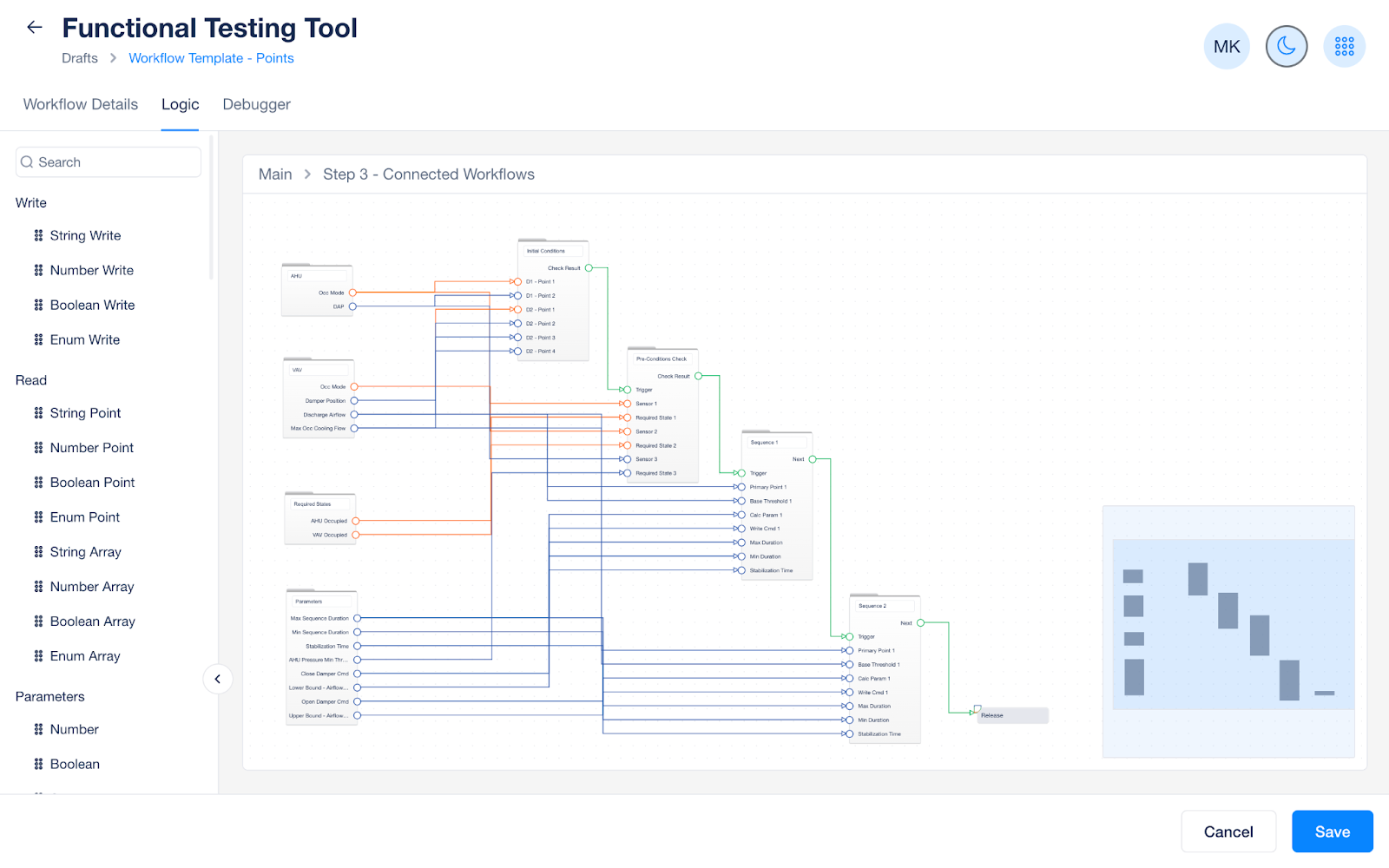
The high level structure of workflow is now complete and we can go through and build each sequence.
Building a Sequence
In this section, we will detail the process of editing the sequence architecture to fit the specific needs of the sequence. We will start with the first control sequence and we leave the Initial Conditions and pre-conditions check folders until the Building the text output section.
This section focuses only on the logic and we will ignore the string builders.
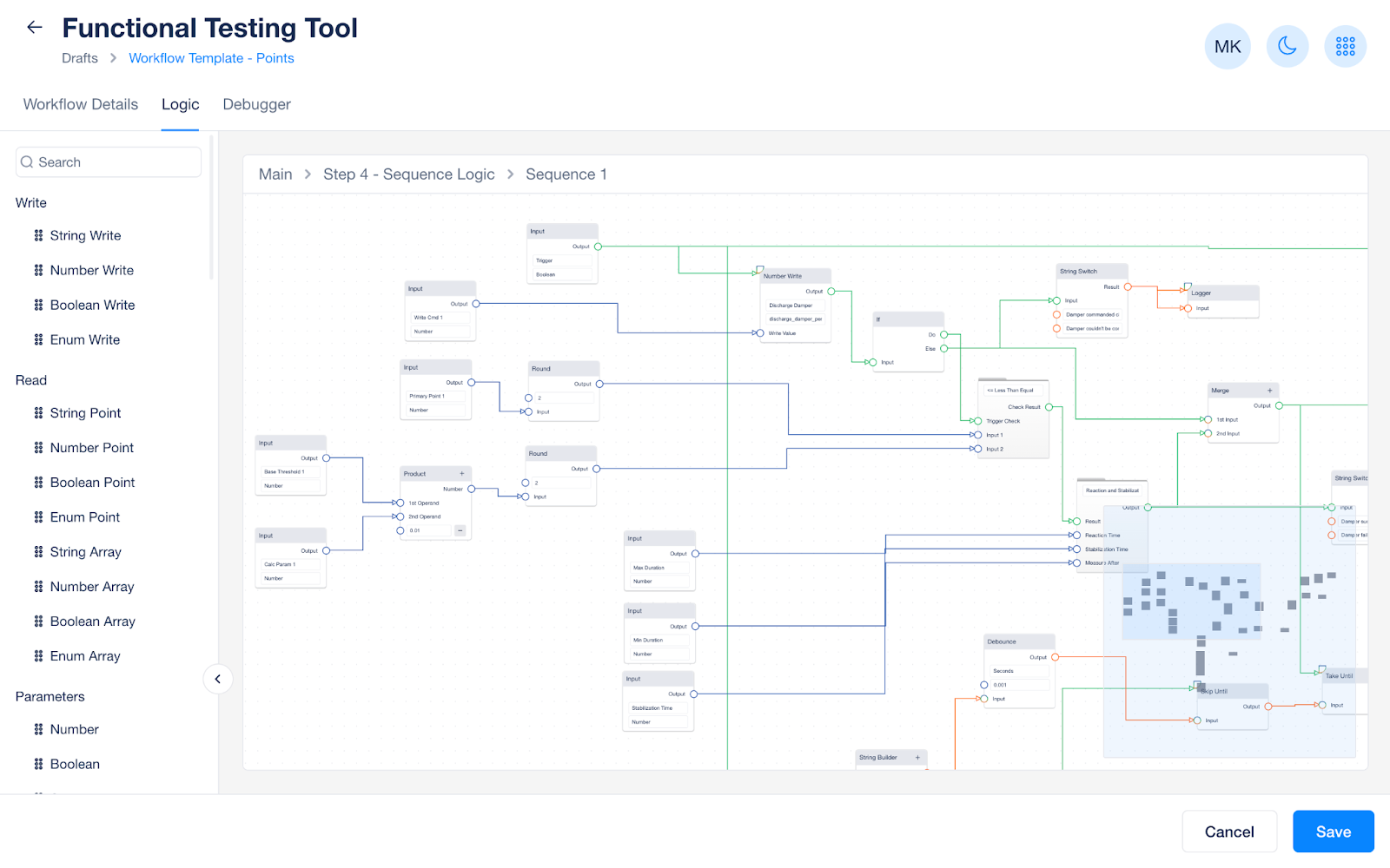
When reviewing the default sequence architecture, you need to ask yourself
Am I writing the correct point field?
Am I doing the proper calculation on my base threshold?
Multiplication, Addition, Subtraction
Am I doing the proper comparison?
Less than, greater than, equal to
For cases, when you are controlling more than one point or have more than one success criteria, see the scaling to more complex use cases section. Don’t worry, those are just as approachable, we only save them for the end for simplicity of this guide.
Building the text output
Now, it’s time to build strings! A deceptively complex part of the process only because we value clear communication which means carefully bringing together all the variables. There will be lots of lines, but we have a couple templates to make it easy.
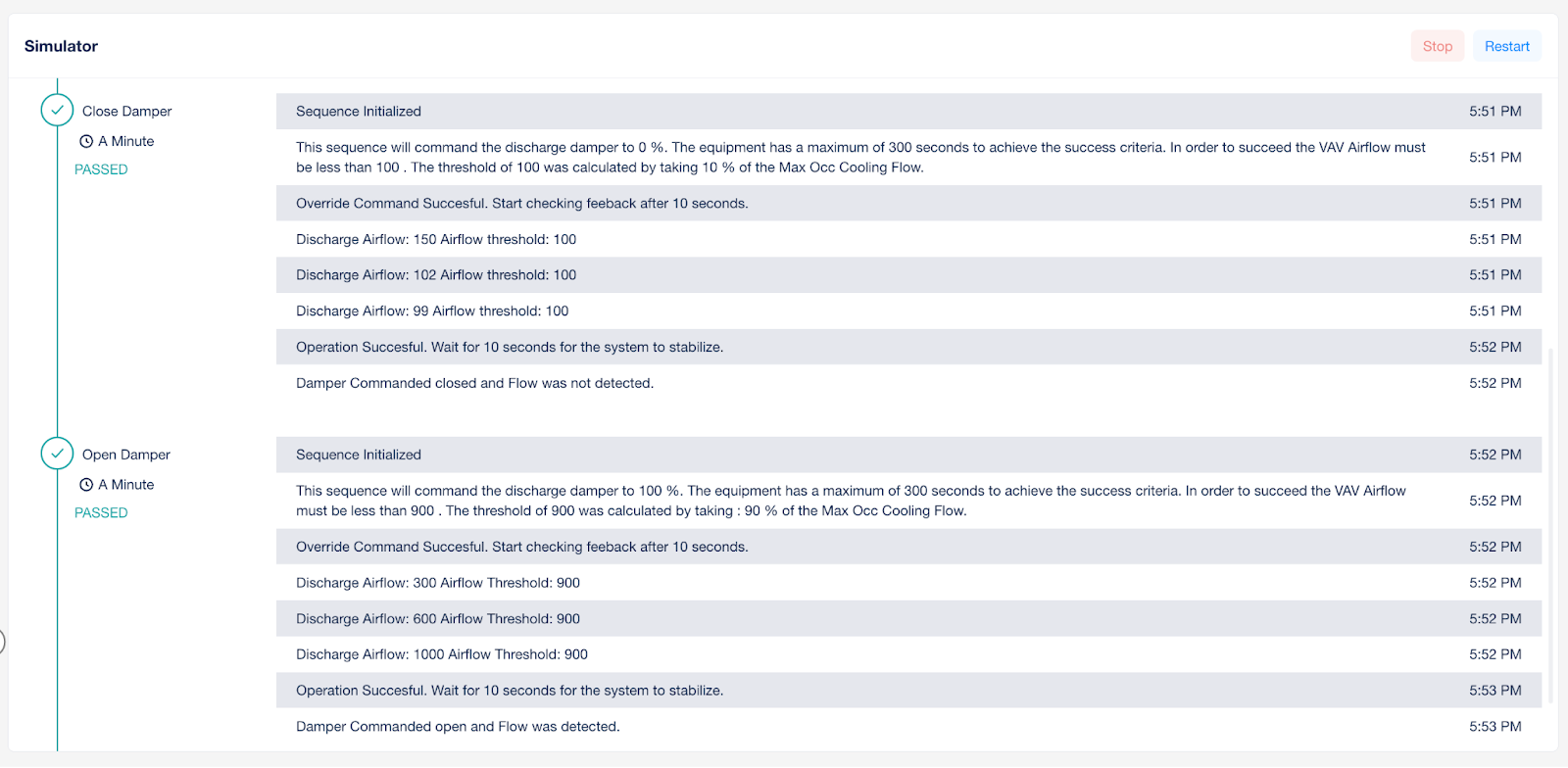
To start, let’s take a look at what the end user sees and we’ll back into how the string builders lead to that output.
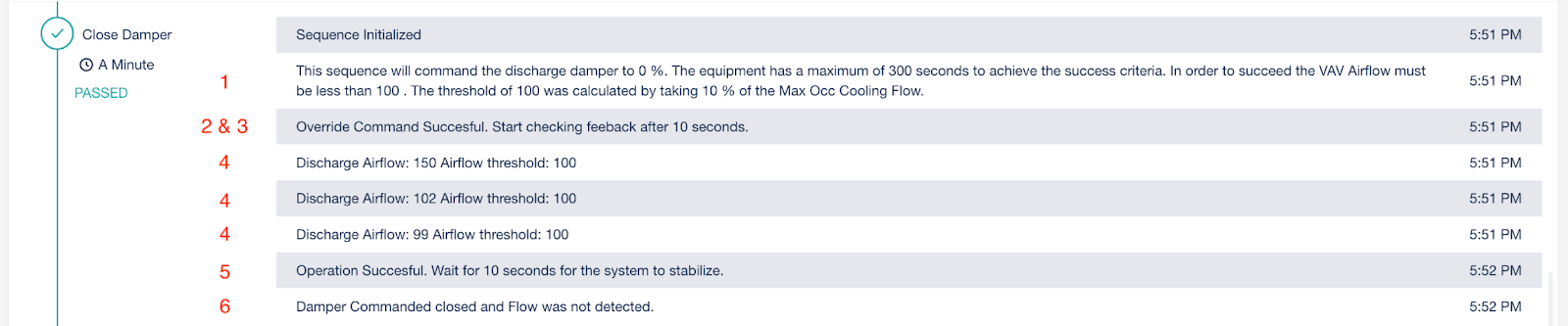
In the above image, we can see the 6 different messages we generate per sequence. Let’s refresh on each of their labels.
Sequence Description Message
Override Success/Failure Message
Minimum Duration Message
Sensor Reading Message
Stabilization Message
Sequence Success / Failure Message
Lucky for us the Override Success/Failure, Minimum Duration, and Stabilization Message are standard messages and generally do not need to be modified. The 3 messages we will modify are the Sequence Description, the Sensor Reading, and the Sequence Success/Failure message.
Let’s walk through these one-by-one. Starting with the simplest.
And don’t forget, to find these in the workflow, refer to the sequence architecture section to see the relative position of each string builder.
Sequence Success Failure
This message outputs at the end of the sequence and is displayed to confirm to the user if the sequence was or was not successful. You should modify these texts directly as needed.
Damper successfully closed.
Damper failed to close.
Sensor Reading Message
This message outputs during the middle of the sequence every time a new point value is received. These messages are relatively easy to build, but will leverage both static text and variable point output. Follow the template below, replacing the purple text with the text relevant to your test. The blue text will be populated by drawing lines in the logic builder.
Discharge Airflow:
Primary Sensor Input:
Threshold 1:
Calculated Threshold 1
Sequence Description Message
This message seems the most straightforward, but will actually require the most inputs and text strings to accurately describe what is being controlled, how long the sequence will last, what are the success criteria, and how are they calculated. While we generally recommend the template below, we have found that it might require a bit of tweaking, depending on your success criteria, to make the language sound right. Replace the purple text with the text relevant to your test. The blue text will be populated by drawing lines in the logic builder.
This sequence will command the VAV Damper Cmd to
Command Value 1
%. The equipment has a maximum of
Max Duration
seconds to achieve the success criteria.
In order to succeed the
VAV Airflow must be less than
Calculated Threshold 1
. The threshold of
Calculated Threshold 1
was calculated by taking :
Parameter calc 1
% of the Max Occ Cooling Flow.
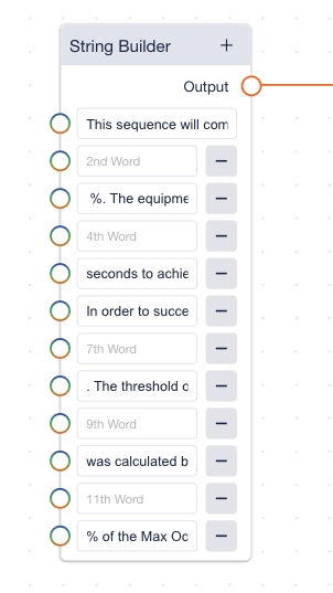
Implementing the string builders
Now that you have prepared each of your messages and their contents, it’s time to implement the string builders. If you have been following the process thus far, it’s just a matter of connecting lines from the already computed variables to their respective position in the string builder sentence. In the example on the right, we see our string builder (corresponding to the sequence description above) ready to receive the input from the logic blocks on the 2nd, 4th, 7th, 9th, and 11th lines.
Initial Conditions String Builder
The strings in this section are simple as we focus on printing the overall description of the workflow and then the initial value of the points per device. You can use the following templates to build your strings for each. Replace the purple text with the text relevant to your test. The blue text will be populated by drawing lines in the logic builder.
Sequence Description
This workflow will test a VAV box for its damper operation. First, we display the initial conditions of the equipment, then we perform pre-condition checks to ensure the equipment is ready to be tested, next we will close the damper and then open the damper measuring airflow to validate the operation.
Device - Initial Conditions
This example assumes a device with two points being printed in the initial conditions. If you have additional points, follow the convention and expand as needed.
Device Type:
Point Name # 1 -
Point Value 1
Point Name # 2 -
Point Value 2
Pre-Conditions Check String Builder
The pre-condition checks come in two forms. A state check which compares if two things are exactly equal or a threshold check which sees if a point is in an appropriate range. Both checks require 2 separate strings one for success and one for failure.
State Check
Success
Device Type
is
Required State
and passes the pre-condition check
Failure
Device Type
is not
Required State
and fails the pre-condition check.
Threshold Check
Success
Device Type
Airflow/Pressure/Temperature does meet the maximum threshold.
Sensor:
Point Value 1
. Min/Max Threshold:
Parameter 1
Failure
Device Type
Airflow/Pressure/Temperature does meet the minimum threshold.
Sensor:
Point Value 1
. Min/Max Threshold:
Parameter 1
Quality Assurance
The primary aim of this section is to arm you with the tools to ensure the test output, text output, and high level design of your workflow all match. Our workflow builder comes with a built in debugger just for this purpose. We recommend the following quality assurance approach on a per folder basis.
Initial Conditions
Testing this sequence is simple. You need to only ensure the text matches the points you are supplying.
For each device type you can ask yourself 3 simple questions:
Am I printing the right device type?
Am I printing the right point name?
Am I printing the right point value?
Pre-Condition Check
Testing the sequence is also straight forward. For each pre-condition, simply check both the success and failure case. Let’s take the VAV Damper Operation example where we have 3 pre-condition checks.
VAV Occupancy
Input an occupied value and verify you print the correct statement.
Input an unoccupied value and verify sure you print the correct statement.
AHU Occupancy
Input an occupied value and verify you print the correct statement.
Input an unoccupied value and verify you print the correct statement.
AHU Pressure above Threshold
Input a pressure above the threshold and verify you print the correct statement.
Input a pressure below the threshold and verify you print the correct statement.
Sequence(s)
The primary things we want to test for sequence operation are
Am I calculating the right threshold?
Does my sequence pass when I reach the threshold?
Does my sequence fail when values approach, but do not reach the threshold?
Do my strings for sequence description and sensor reading look consistent?
Scaling to more complex use cases
Control Logic
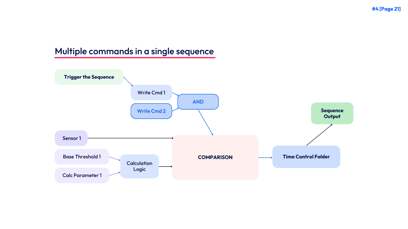
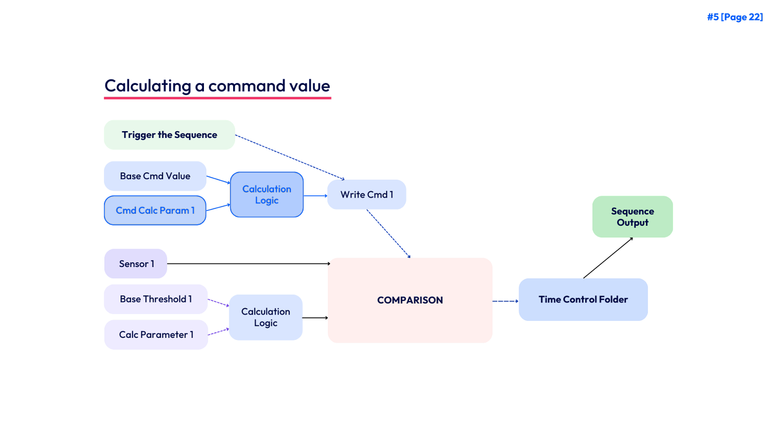
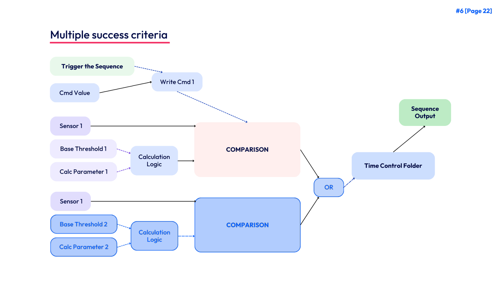
Often we run into use cases that require us to expand into multiple write points, calculated command values, or multiple success criteria. Below we provide a simple visual guide of how to expand these use cases within the architecture. We present these individually, but the logic can be combined into a single sequence if needed. We focus on the control sequence,
Writing multiple commands in a single sequence
Calculating a command value
Multiple Success Criteria
String Builders
Below we provide a sample of how the string builder can be expanded for multiple success criteria. We leave it as an exercise for the reader to construct string builders for any other complex use cases.
Multiple Success Criteria
This sequence will command the VAV setpoint to
Calc value 1
The equipment has a maximum of
Max Duration
seconds to achieve the success criteria.
In order to succeed the VAV DAT must be less than
Calculated Threshold 1
or less than
Calculated Threshold 2
. The threshold of
Calculated Threshold 1
assumes that when heating is stopped the VAV discharge air temp will approach the VAV zone temp with a buffer of
Calc Param 1
. The threshold of
Calculated Threshold 2
assumes that when heating is stopped the VAV discharge air temp will approach the AHU discharge air temperature with a buffer of
Calc Parameter 2
Conclusion
Congratulations! If you have made it to this point you have completed your first Digital Commissioning workflow. If this was your first time, it may have took a few hours or days to work through this guide, but with a few rounds of practice you should be building workflows in minutes.
We look forward to hearing about the results and any questions you may have. Feel free to contact your account manager or [email protected] for any additional questions or feedback.
Appendix
This guide focuses only on the creation of workflows. If you want to learn more about Digital Commissioning or our Logic blocks check out the functional testing section of our knowledge base.
Definitions
Time Control Parameters
KODE Labs standard architecture uses three (3) time control parameters in every workflow. These are user adjustable and as a standard are applied the same to each sequence within the workflow.
Related Articles
Running a Functional Test
Functional Testing is a digital commissioning tool to validate equipment operation. KODE Labs supports a variety of tests on a variety of equipment, but it is most commonly used on zone controllers such as Fan Coils, VAVs, and Heat Pumps. Running a ...Functional Testing Tool (FTT) Dashboard
Functional Testing serves as a digital commissioning tool designed to validate the operational functionality of the equipment. KODE Labs accommodates a diverse range of tests applicable to various types of equipment, with its primary usage centered ...FTT Projects
Hello there ? If you’re reading this then you’re well on your way to functionally testing your building. To get started, enter the main FTT page from the left sidebar on KODE OS. In the 3 dots, you will see projects. The idea is to create a ...Graphic Tool Settings
In the settings of Graphic Tools (Global Configuration) you can find everything that is needed to configure like Layers, Smart Markers, Icons and also here you can upload different graphic files for floor plans, devices and systems to use later while ...Add Custom Icons
To add custom icons and ranges to represent each device type and value into a system or floor plan follow the below steps: Navigate to Admin module by clicking on the profile icon from the left main navigation bar. From the left side menu of the ...