Floor Plan & System Graphics
Placing devices into floor plans
The goal of floor plan placement is to put each of the equipment in its intended location in the building for quick and easy viewing.
Follow the below steps for further instructions.
Navigate to a building of your choice through the Sites feature in the left navigation bar.
Click on Areas and the list of floors of that building will show up.
Click on the floor which you wish to place devices on the floor plan for.
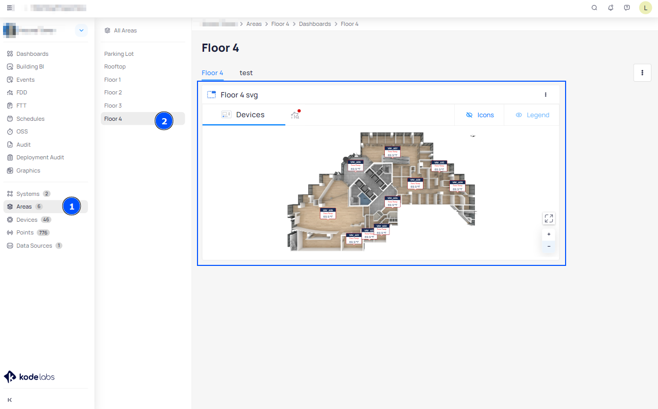
Select the three dots on the dashboard and click Edit.
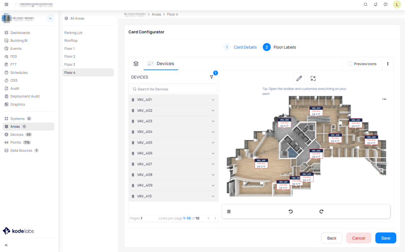
Additional layers can be selected by using the layers icon in the upper left. When a layer is selected it auto generates a tab that can be used to filter to devices of that type.
Tip: Starting with the device tab will allow you to utilize autosuggest later.
Starting with the device tab, drag equipment from the list on the left onto the floor plan.
You can zoom in to get more precise.
You can modify the placement of the device by dragging on the triangle.
Device layer is intended to show where the device is physically installed and located, whereas the temperature layer is intended to reflect the location of the temperature sensor within the unit.
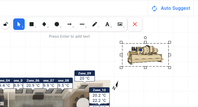
Click on the thermometer (temperature) icon to switch over to the temperature tab (or any other layer).
Click on the Auto Suggest button in the upper right to map the equipment you just placed.
You have now placed your devices on the floor plan of the area of your choice.
Customizing Markers and Icons
The Graphic Tool feature provides different tools which allow you to optimize and make floor plans more intensive
from where you can view and spot devices’ performance with a single sight. This will give you an overall visual
perspective of what is happening on the floor.
You can add texts into systems and floor plans with different fonts, draw custom shapes using the pen tool, add
images and different colors to create gorgeous graphics that you can customize with powerful features.
Add and Edit Markers
The Graphic Tool feature allows you to tweak the colors of the markers in systems and floor plans and style them
visually.
Tweak the sizes and align marker titles.
Change the background color of the marker and edit font colors for devices and points text.
Make your own marker style and save to use it again.
To be able to style the Floor Plan markers to your liking, navigate to Floor Plan > click on the three dots at the top
right hand corner of the floor plan widget > select the layer of your choice e.g. Temperature, Lighting, Fire…
Edit a Marker
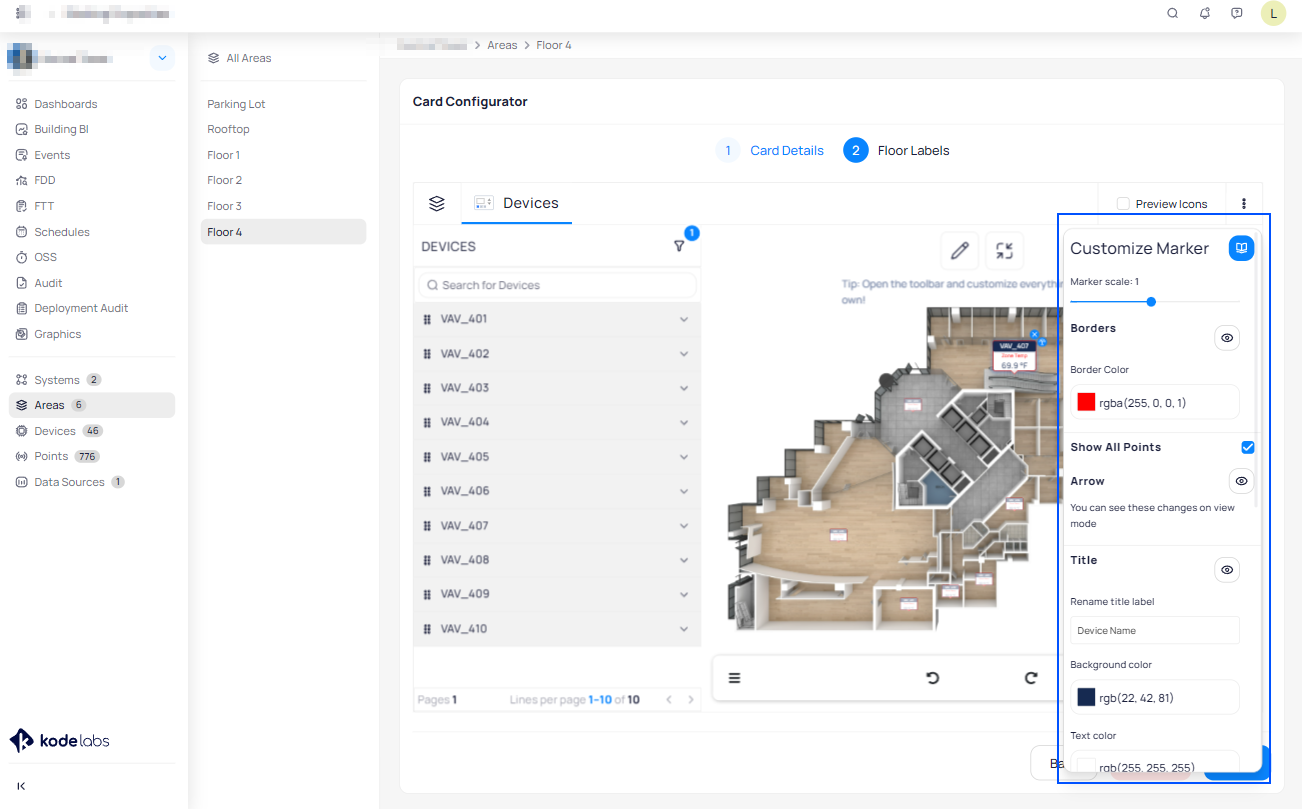
Clicking on each marker, it will open up a sidebar “Customize Marker” page, from where you can:
Adjust the marker style by sliding into the “Marker scale” slider bar
Rename Title Label/Device Name and Point Name.
Change the Border, Background and Text color.
Align title label (left, right, top, button).
Represent a point with an icon
Enable Marker Icons by switching on the slider button
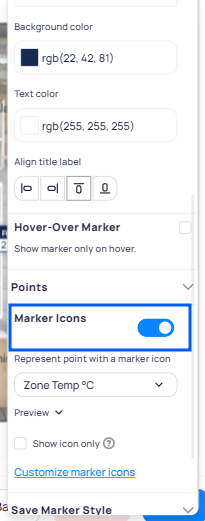
Choose an Icon Group from our default Graphics or from the Custom Graphics created. See here how to create custom icons with custom value ranges.
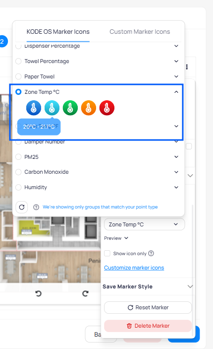
You can choose to show only the icons by clicking on the “Show as icon only” checkbox.
Note: Clicking that checkbox will show only the icon, it will not show the point value. You can always go back and
change it.
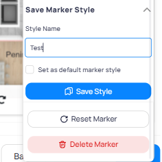
You can save your marker style for later use or set it as the default marker style which will apply to all new added markers.
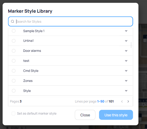
To see the saved styles click on icon next to the “Customize Marker” title, you can use them for other markers and choose one to be a default marker style.
Add Custom Icons
To add custom icons and ranges to represent each device type and value into a system or floor plan follow the
below steps:
Navigate to the Settings module while on portfolio level.
From the left side menu of the Settings page select Marker Icons
At the top right of the page you will see 3 tabs: KODE Library, Custom Library and All Icons
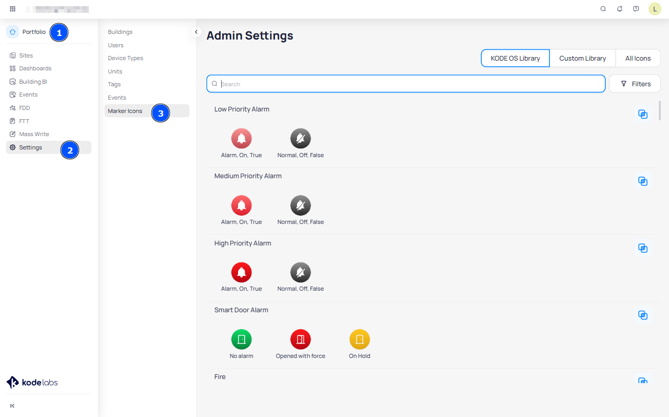
KODE Library
At KODE Library you will find the list of the default icons and their values for each Category (e.g. Temperature,
Fire, Parking, Battery Status).
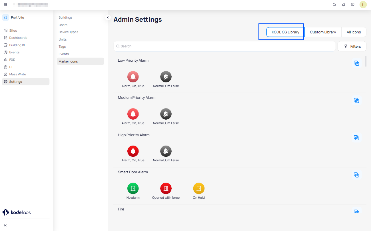
Clicking on the Duplicate iconof each group you can duplicate the category and customize it to your liking.
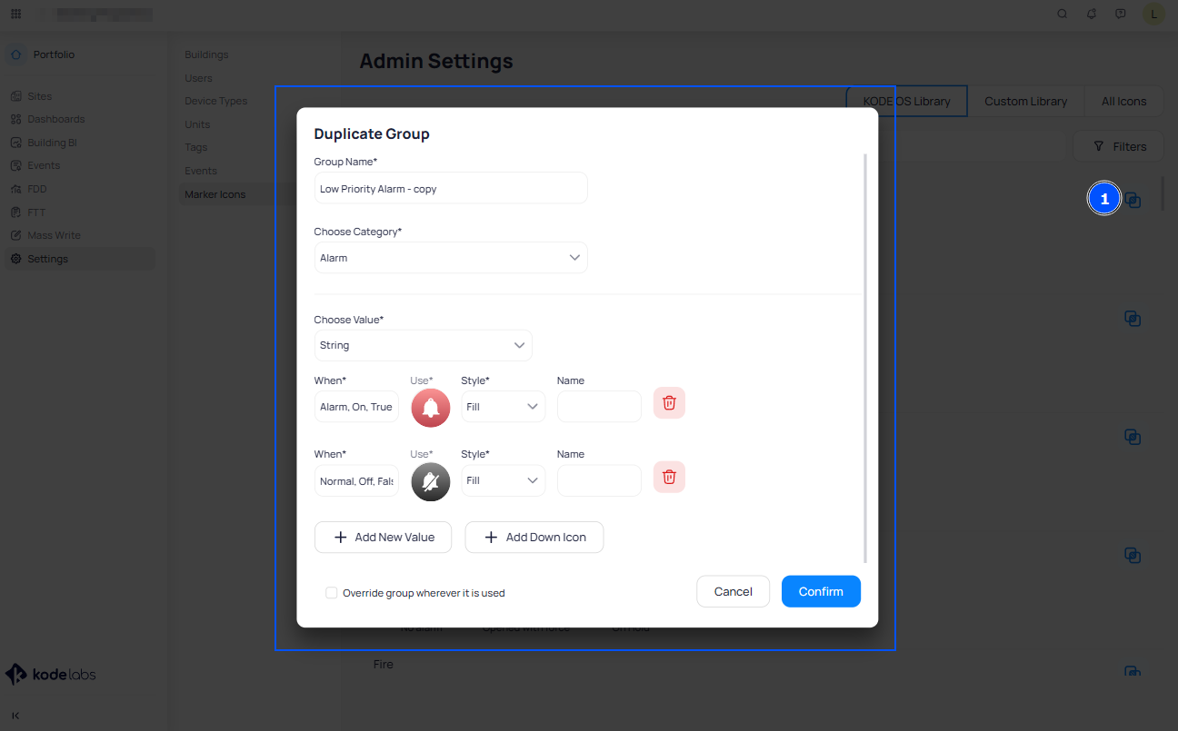
Once clicking on Duplicate you will be directed to the "Duplicate Group" page from where you can:
Give a name to the group
Choose a Category
Choose the Value (Number or String)
Add new values
Use the default icons or add new ones
Once you customize the group to your linking, click on Confirm and the group will be added to the Custom Library
tab.
Custom Library
In the Custom Library you can Edit, Duplicate and Delete your custom groups or add a New group from scratch.
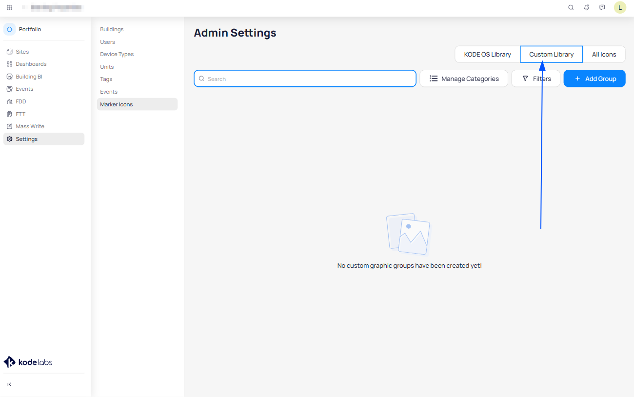
To add a new group click on the plus icon at the bottom right of the page.
On the “Create a Group of Graphics” page, add the group name (e.g Zone Temp), choose the category (e.g. Temperature), value (e.g. Number), unit (e.g Celsius).
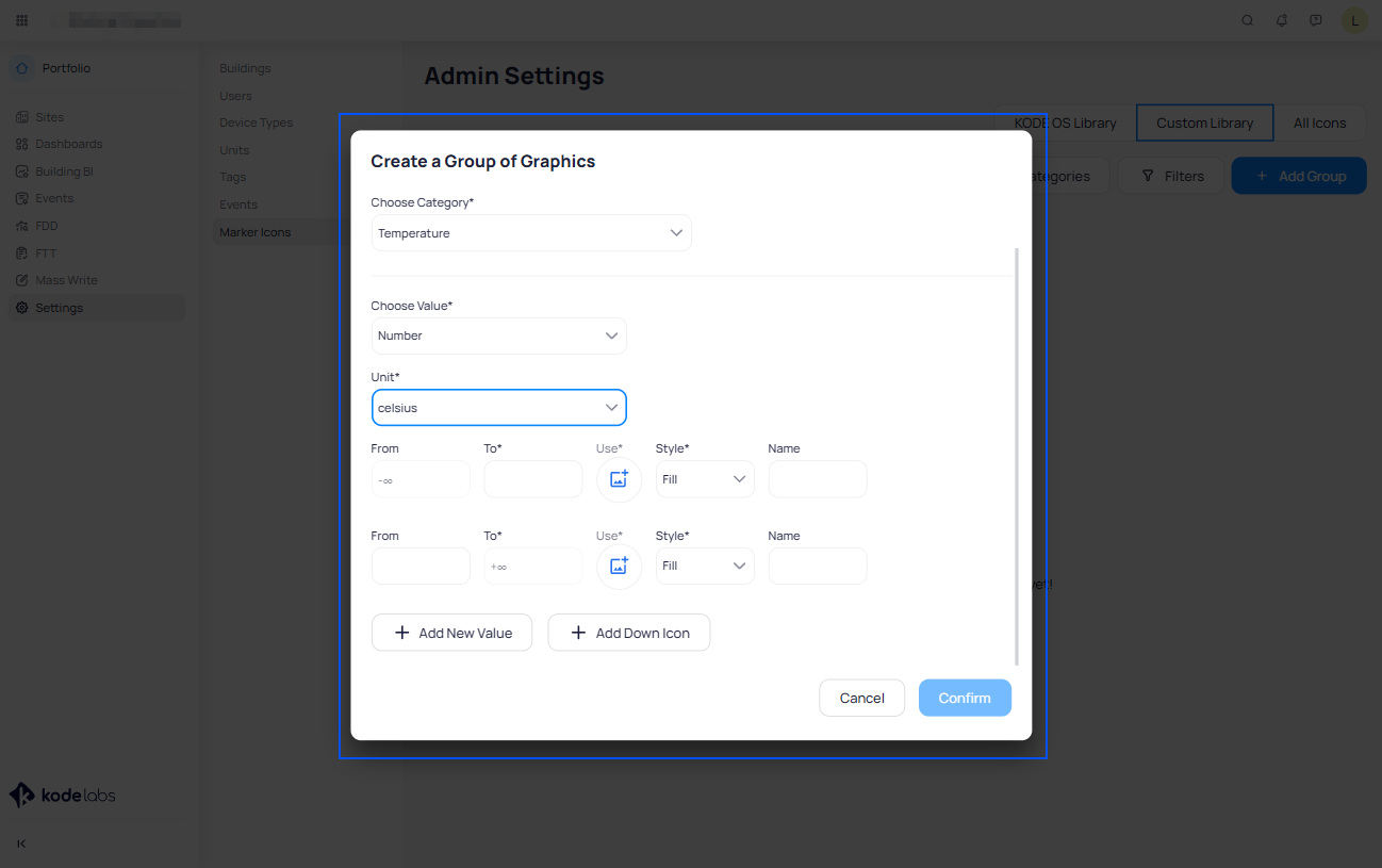
Clicking on the “+Add new value” button, you will add a new value between the other values.
Clicking on the “+Add down icon” button, you will add an icon which represents down devices into floor plans or systems.
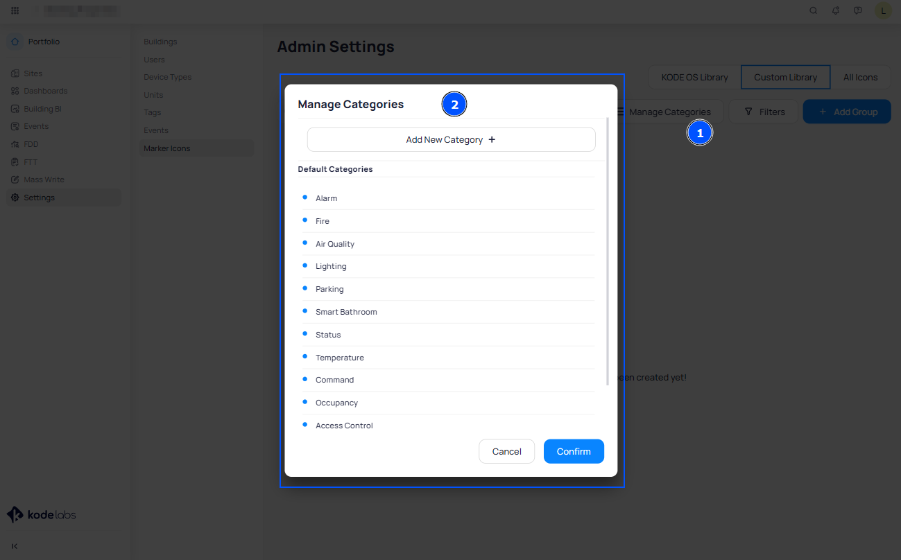
Manage Categories
To add a new Category, click on the “Manage Categories” button at the top right of the Custom Library page.
In the pop up page that opens up click “+Add new Categories”
Write down the Category Name
Click on the + Icon well next to the category name
Click on Confirm
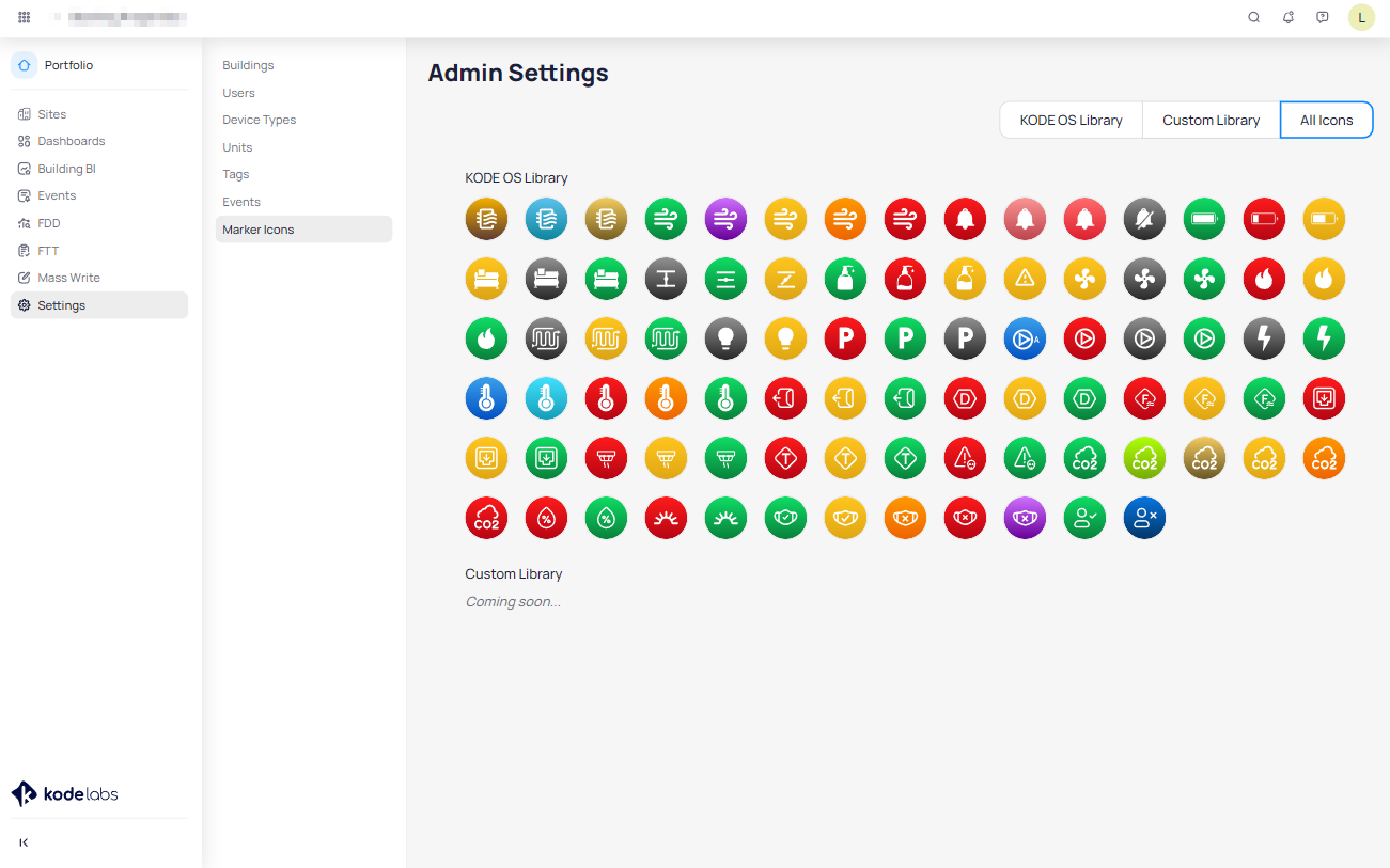
All Icons
At the “All Icons” page you will see all Kode Library icons which are the default icons and all your custom icons
from the Custom Library section.
To add a new icon which you can use to represent a point value on the floor plan or system graphic, click on the
+ icon at the bottom right of the page.
At the “Add New icon” popup page give the icon a name
Click on the Imageicon to add a new icon from your computer.
Once you insert the icon, click on Confirm to be able to use and choose it while adding new groups of graphics to
represent a point value.
Floor Plan Graphic Customization
You can add texts into floor plans with different fonts, draw custom shapes using the pen tool, add images and
different colors to create gorgeous graphics that you can customize with powerful features.
You can enhance the design of a layout in a number of ways, including:
adding text, consistent styles, colors or effects
using the drawing tools to add lines, rectangles, or other shapes
adding an image
insert link to a shape, text or image
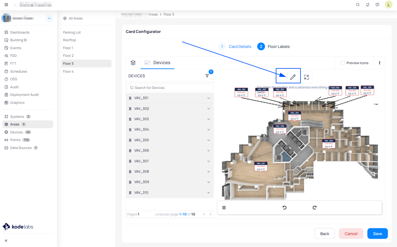
To add and customize different shapes, images and texts click on the Toolbar icon at the top center of the floor
plan or system graphic.
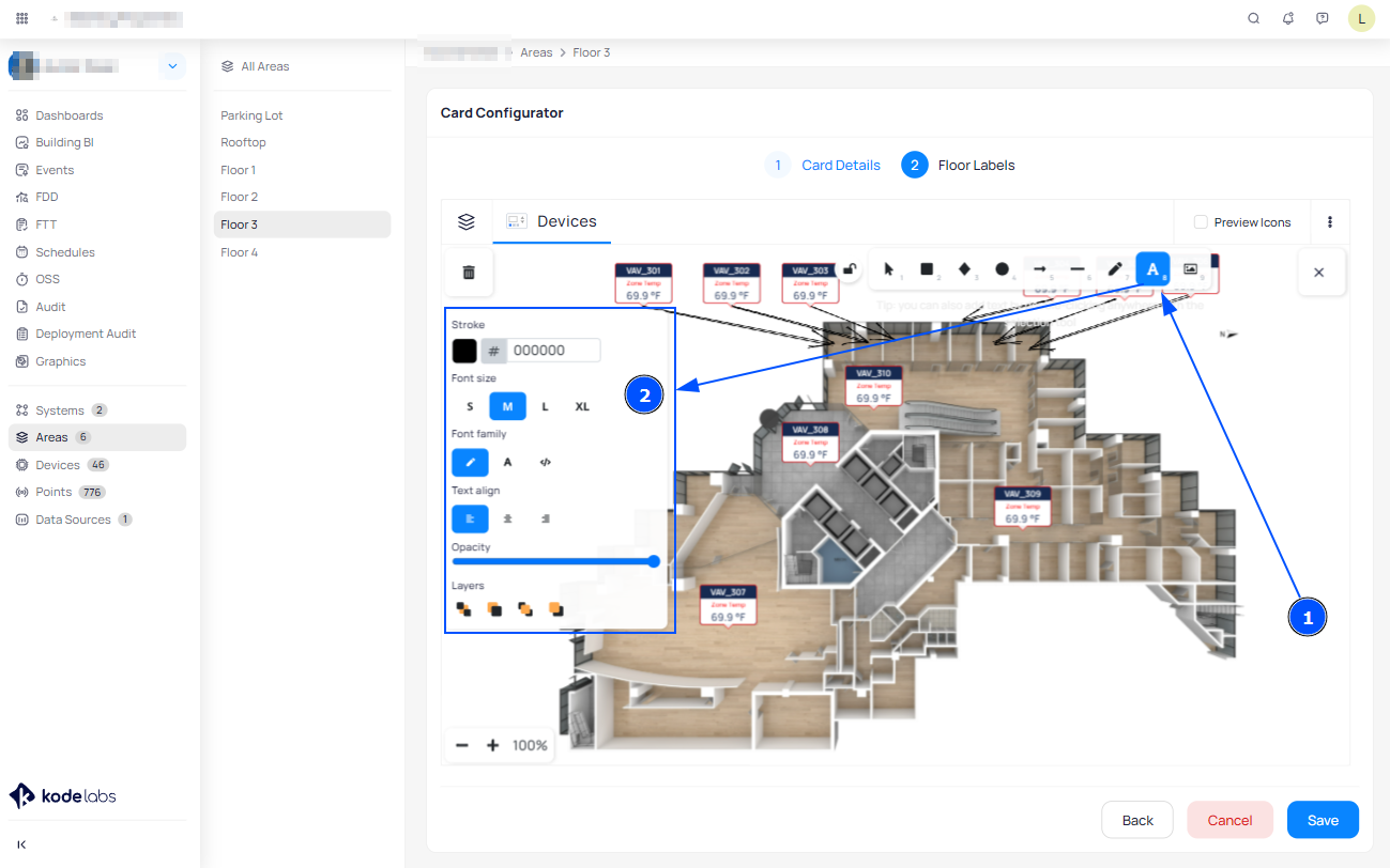
Adding Text
You can add text into systems and floor plans to make it easier to use and understand.

To type text on a layout, click on the toolbar icon to open up the tool menu:
Click on the Text tool iconor double click on the surface to activate the Text tool.
With the crosshair pointer:
Click where you want to add text
You will see a blinking insertion point
Type the text
To change the text angle:
Select the text to rotate
Click the circle at the top of the selected text and keep the left-hand button of the mouse pressed
Rotate until the text is the angle you want
To set text formatting options such as font, style, size, text color, and alignment, use the sidebar popup page that opens up once you add the text.
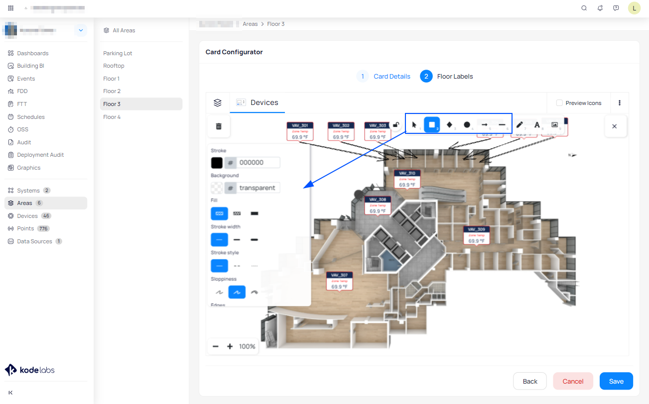
Drawing arrow-line, lines and other shapes
To create a rectangle, circle, or diamond shape:
Click the rectangle tool, diamond toolor circle tool
Position the crosshair pointer on the layout where you want the object to begin.
Drag the crosshair pointer until the object is the size that you want.
After you add a shape or prior to adding it, you can customize it in a number of ways by using the tool sidebar popup page. You can change the look of the shape by changing its fill or by adding effects to it, such as soft edges, adjust stroke color, width, style, and sloppiness.
You can also add text inside a shape by selecting the shape and pressing Enter or double clicking the interior of the shape.
You can fill the shape with a color - solid color or hachure and cross-hatch.
To change the object angle:
Select the object you want to rotate
Click the circle at the top of the selected object and keep the left-hand button of the mouse pressed
Rotate until the text is the angle you want
To create an arrow-line or line:
Click the Arrow toolor Line tool
Position the crosshair pointer on the layout where you want the line to begin.
Drag the crosshair pointer until the line is the size that you want.
To create an object that is constrained to a certain angle or shape, do one of the following:
Click on the surface where you want the line to begin
Drag for a single/straight line
Click to start multiple points and do curved sharp or angled lines
You can always customize the lines by using the sidebar tool popup page.
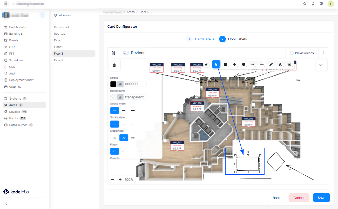
Editing Objects - Selection Tool
To edit one or several shapes, lines or texts, change its positions, arrange, resize them, and make other changes to
their appearance you can use the Selection tool.
Selecting objects:
Clicking in the Selection tool, the pointer becomes an arrow pointer from where you can.
Select one object
With the arrow pointer, click the object.
Select several objects at once
Drag the arrow pointer to make a selection box that includes the objects. The selection box has to completely surround the objects. To avoid including partially selected objects and prevent dragging, press Ctrl as you drag.
You can change the fill color, position, size, angel, stroke color of multiple objects once selected using the tool sidebar popup page.
To change the object angle:
Select the object you want to rotate
Click the circle at the top of the selected object and keep the left-hand button of the mouse pressed
Rotate until the text is the angle you want
Add Images
To insert an image to the floor plan or system:
From the toolbar click on the Image icon
Choose an image from your computer
Position the crosshair pointer on the surface where you want to place the image.
Resize by dragging the image edges until the image is the size that you want.
To change the image angle:
Select the image you want to rotate
Click the circle at the top of the selected object and keep the left-hand button of the mouse pressed
Rotate until the image is the angle you want
Customize Drawings
To begin drawing simply click on the Pencil Icon and you're ready to start drawing.
Move around and draw to your liking while keeping pressed the left-hand button of the mouse.
You can always customize the color of your drawings by using the sidebar tool popup page.
To change the object angle:
Select the object you want to rotate
Click the circle at the top of the selected object and keep the left-hand button of the mouse pressed
Rotate until the text is the angle you want
Add Pre-Defined Drawings
To add predefined drawings click on the Toolbar icon at the top center of the floor plan or system graphic.
Click anywhere on the floor plan surface and then from the keyboard press number 0 at the top of the keyboard.
Click on the folder icon to add items from your PC.
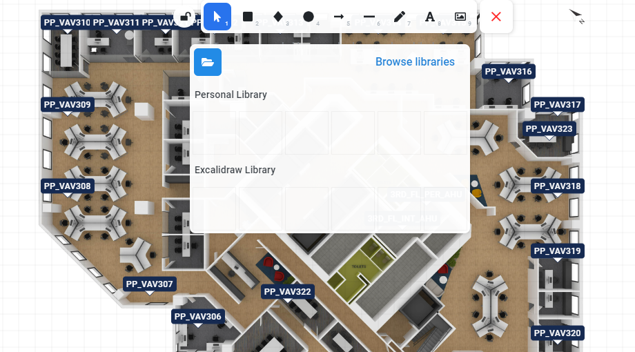
Click on Browse libraries and select a group of icons you want to add to the floor plan.
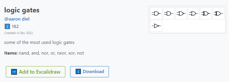
Click on the "Add to Excalidraw" button.
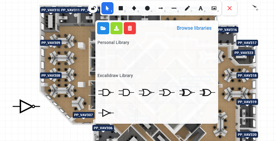
A new tab will open up which will direct you to the floor plan edit mode, from here click on the Toolbar icon at the top center of the floor plan or system graphic. Click anywhere on the floor plan surface and then from the keyboard press number 0 at the top of the keyboard.
The selected group of icon will show up which you can use and add to the floor plan.
Shortcuts to help you in moving through your work quickly and easily
Ctrl+Z: Undo
Ctrl + A: Select All
Ctrl + C: Copy
Ctrl + V: Paste
Ctrl + X: Cut
Delete: Delete
Advanced Shortcuts:
Shift+Alt+C: Copy to clipboard as PNG
Ctrl+Alt+C: Copy Styles
Ctrl+Alt+V: Paste Styles
Ctrl+[: Send Backward
Ctrl+]: Bring Forward
Ctrl+Shift+[: Send to back
Ctrl+Shift+]: Bring to front
Shift+H: Flip Horizontal
Shift+V: Flip Vertical
Ctrl+K: Create Link
Ctrl+D: Duplicate
Check the below video to see a simple walk-though floor plan graphic customization.
System Configuration
KODE OS allows you to review, monitor and see all details of major systems.
Select the building of your choice by clicking “Sites” on the left Main Navigation bar.
From the left main menu select “Systems”.
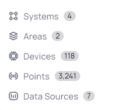
A page with the list of all Systems will show up.
Search and Select a System.
Upload System Graphic
Upon selecting the System you will be directed to the System Details View.
To Upload System Graphic click on (Pencil) icon.
Once clicking it you will be directed to the system Edit mode from where you can upload new or change the existing system graphic.
Add or Change the graph by clicking on Add/Change Background button.
Select an SVG or PNG to upload from your computer.
Add Devices to the System
To Add Devices into the System click on(Pencil) icon from the system right sidebar.
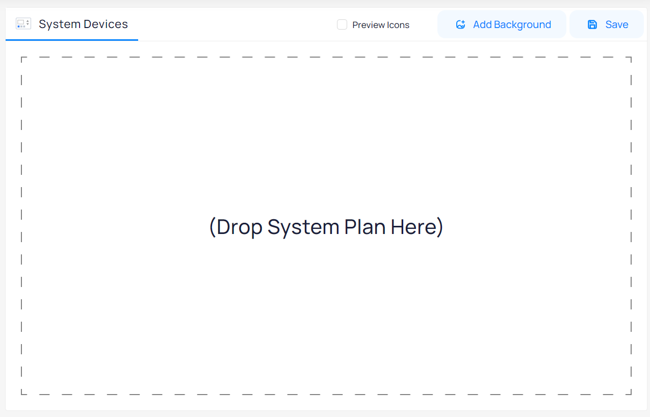
Once clicking it you will be directed to the System Devices from where you can modify and add more devices.
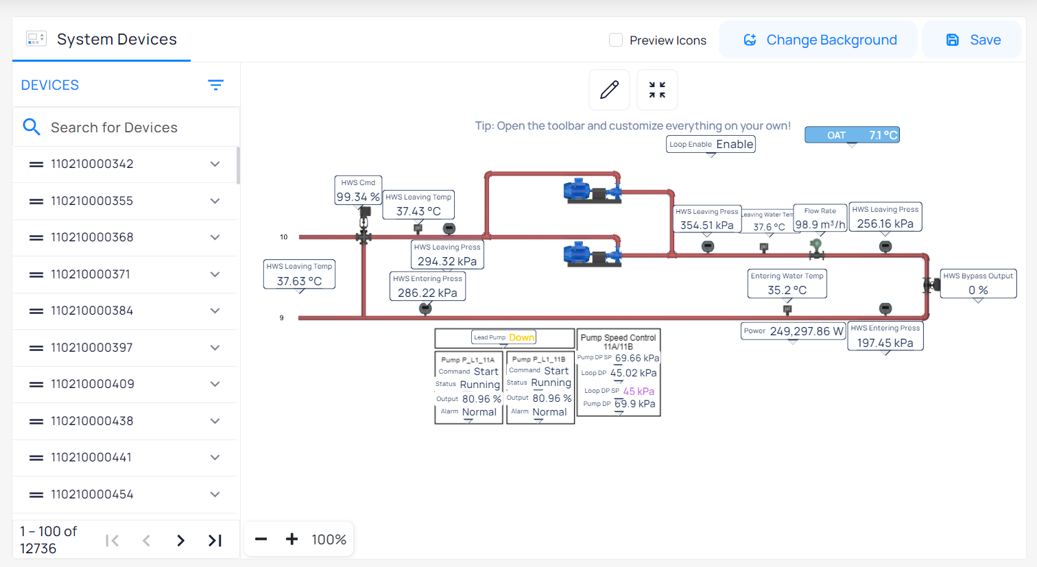
In order to be able to add devices and points into the system, a system graphic should be uploaded (png or svg format)
On the left side of your screen you will see the list of all Devices.
Filter the devices Type and Area by clicking on the Filtericon.
Clicking on the arrow next to each device name it will open up a drop down menu where all points of the selected device are located.
To make a Device and its Points visible on the Circuit View simply Drag and Drop a device or point from the device list into System Graphic.
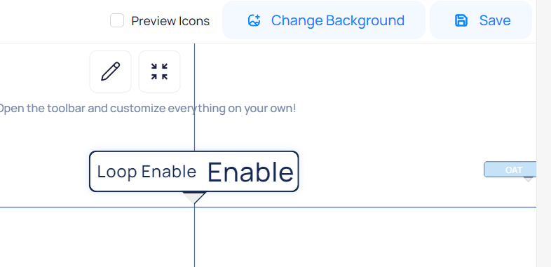
To rearrange device markers on Circuit View:
Drag and Drop Device markers by the arrow.
Zoom in and out to be more precise.
Click on the Save icon at the top right of your screen and your changes will be saved.
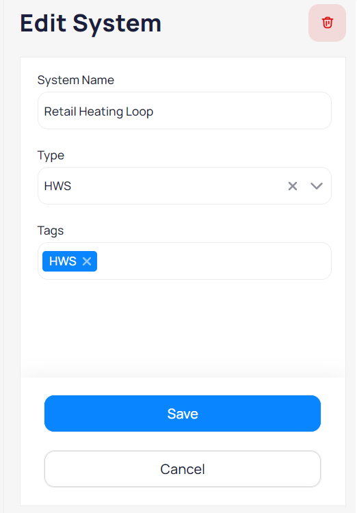
Delete Systems
To Delete a System:
Click on the Delete icon which will appear once clicking on the Edit icon.
Related Articles
Graphics
What is included There’s a graphics builder we’ve been cooking that gives you the ability to build System and Device Graphics and customize floor plans with additional functionality that outperforms any other graphic tool in the industry. Smart ...Navigating to Area Insights - Mobile App
To obtain a visual representation of device placement across floors and other areas, and to interact directly with the devices, you can rely on Floor Plans. Each area will have its own Dashboard with various widgets. When you enter the Floor Plan ...Navigating to Systems - Mobile App
In order to obtain a visual representation of device placement throughout major systems and interact with the devices directly, you can rely on the Systems module. Navigate to the building of your choice and select Systems on the Building Menu. A ...Areas
Accessing Areas To access Areas just go on the left pane and click at “Areas” . Once you are in the Floor Plan view you will be prompted with several options and features that you can benefit in order to enhance your experience. Depending on the type ...Hot Water System Faults
Hot Water Diff Pressure Less than Setpoint ☝️ Event: Alerts when hot water pumps are not able to meet the differential pressure setpoint. Priority ? Critical Domain ? Heating Operation Failure Tuning Parameters Display Hint Alarm On Delay [15min] ...